


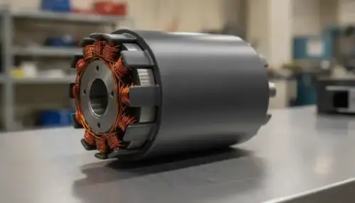
How electric motor overmolding works is a process question, not a catalog question. A wound stator or rotor is placed in a mold. Molten plastic or a curing resin fills the designed cavities. The cooled part leaves with slot insulation, end features, and locating geometry formed in one shot. The result only works if the fill is complete, the copper stays where the design put it, and the insulation system still passes at the motor’s real temperature.
Call (813) 468-3036 about your overmolding requirements, or see when a custom electric motor fits the application.
How electric motor overmolding works in practice
Overmolding here means insert molding. The laminated core, and often the wound coils, is the insert. Plastic does not replace the steel or the copper. It bonds to them and takes the shape of the mold around them.
A typical stator shot does several jobs at once:
- It covers the slot walls so magnet wire does not touch the steel.
- It forms end insulation and a base for the stack.
- It can add wire guides, pole pockets, connector features, or a lead exit.
- It can hold a bearing, a cover, or a mounting face in a later shot.
Paper slot liners and separate end caps can do parts of that work. They need more pieces and more assembly steps. One mold can replace that stack of parts when the geometry is stable and the volume supports the tool. Composite Motors designs and runs injection overmolding for low, medium, and high volumes, next to custom winding. The right route still depends on the print, not on a blanket process choice.
The sequence is short to describe and strict to control. The stack is loaded into the cavity, centered, and held by slides or cores as the mold closes. Plastic is injected, packed, and cooled or cured. The part is ejected, and the next insert goes in. A published mold study of plastic-coated stators described a robot-loaded tool running a full cycle in 26 seconds, with the stack placed to a few hundredths of a millimeter. That number belongs to that tool. It is not a promise for every motor.
What has to be true before the mold closes
Most failed overmolds are designed before the press starts. The insert, the plastic, and the tool have to agree on three things: where the plastic must go, where it must not go, and how the copper survives the shot.
Insert condition
The lamination stack needs a datum the mold can find every time. Burrs, loose laminations, and oil film change both the fill and the dielectric path. If the part is already wound, lead dress and phase insulation have to sit inside the steel envelope the cavity expects. A lead that springs out becomes a short or a blocked gate.
Magnet wire enamel is an electrical film, not a mold-release coating. It can crack if a core presses on it, or it can soften if the melt temperature and dwell are wrong for that enamel. The winding method matters here. Hand winding is a common prototype and low-volume route. Automated winding is the usual higher-volume route. Either one can be overmolded, but the wire positions have to match the cavity, not the other way around.
Fill, knit lines, and thin walls
Slot insulation is often well under a millimeter. Thin walls need a plastic that flows at the real mold temperature, and gates placed so the cavity fills before the flow freezes. Knit lines in a slot wall are dielectric weak points, not just cosmetic marks. A void at the slot bottom is worse. It is an air path from copper to steel.
Complete fill is the first quality gate. If the part is not full, no later electrical test can make the missing plastic appear. Gate location, venting, and pack pressure are set for that reason. Bright, uncoated yoke faces are a separate sealing problem. The tool has to shut off on the steel so plastic does not flash onto a surface that must stay bare.
Heat and stress during the shot
Thermoplastic overmolding puts a hot melt against a cold, or only warm, metal insert. High-temperature plastics such as glass-filled PPS are often processed with mold and melt conditions that reach about 250 °C in published stator tooling. That heat is brief. It is still enough to move a poorly supported coil or to stress the enamel.
Thermoset processes, including epoxy transfer molding, cure in the tool instead of freezing as they cool. They can wet fine features well. They also lock in cure shrinkage. Neither family is automatically better. The choice follows the thermal class, the chemical exposure, and whether the part must be reworked.
Materials, heat, and the insulation system
The plastic is not chosen from a data sheet in isolation. In a motor it touches magnet wire, ground insulation, steel, and sometimes a bearing or connector. Those materials age together.
UL 1446, the Standard for Systems of Insulating Materials – General, treats an electrical insulation system as the combination of insulating materials and the conducting parts they serve. UL Solutions describes that system view because a film, a resin, and a ground insulation can interact under heat even when each one looks acceptable alone. A full thermal-aging program is how those interactions are found. Swapping a “similar” overmold resin without checking the system is a materials change, not a drop-in.
Three practical limits follow from that:
- The thermal class has to cover the hottest copper, not the average case temperature.
- A higher-temperature plastic does not fix a trapped hot spot. The heat still needs a path into the steel, the housing, or a designed cooling feature.
- Chemical exposure matters as much as temperature. Fuels, cleaners, salt water, and sterilization cycles can attack a resin that is fine in dry industrial air.
Published comparisons of overmolded stator insulation with paper liners point to fewer pieces, easier winding, and a more continuous plastic path for heat. Those are design advantages when the wall is complete and the resin matches the duty. They are not a measured efficiency gain for a motor that has not been built yet.
Overmolding is also not the same as every other coating Composite Motors applies. Vacuum-pressure impregnation soaks varnish into a wound slot. Parylene is a thin conformal coat. Hermetic packaging uses metal, ceramic, and glass seals around electronics. Use the process that matches the failure you are trying to stop. Do not treat them as interchangeable seals.
Overmold, varnish, and hermetic packaging
Engineering teams often arrive with a sealing word already chosen. The table below separates the processes by what they actually do. Ratings in the right-hand column are confirmation items, not catalog numbers.
| Process | What it forms | Best used when | What to confirm |
|---|---|---|---|
| Injection overmolding. | Slot insulation, end features, and locating geometry in plastic. | The geometry repeats and the tool can shut off on steel and leads. | Fill, knit lines, enamel survival, and the insulation system. |
| Varnish or VPI. | Resin inside an already insulated winding. | The slots already have liners. The goal is bond and moisture resistance. | Resin compatibility with the existing insulation system. |
| Parylene coating. | A thin conformal film on exposed surfaces. | The need is a thin barrier, not a structural wall. | Coverage in crevices and any masking of contacts. |
| Hermetic package. | A metal or ceramic enclosure with glass or ceramic seals. | Electronics must stay dry through pressure, autoclave, or long storage. | The seal design and the model-specific thermal and electrical ratings. |
A stator can use an overmold and still sit in a larger assembly that is sealed another way. The overmold answer does not set the controller package, and a hermetic controller rating does not describe the stator plastic.
Design checks that decide if the shot will hold
Before a tool is cut, the mechanical and electrical models have to describe the same part. Composite Motors uses overmold design with motor and mechanical design, including FEA, when the application needs that work. The checks below are the ones that change the mold, not the ones that decorate a slide.
- Shutoff map. Mark every face that must stay free of plastic, including bores, end faces, and connector pins. If the shutoff is a guess, the first shots will flash or leave bare steel in the slot.
- Wall and knit map. Set the minimum insulation thickness and put knit lines away from the shortest copper-to-steel path. Add a vent where the last air will sit.
- Lead and insert stack-up. Define how leads, phase insulation, and any bearing or bushing are held during close. A feature that moves under pack pressure needs a core, not a note on the print.
- Thermal path. Name where copper loss goes. Plastic can spread heat into the stack. It can also wrap a hot spot if the wall is thick and the only exit is through the resin.
- Process window. Record melt or cure temperature, mold temperature, pack, and cool or cure time against the enamel and the plastic, not against a generic press setting.
- Service environment. Write the fluids, temperature cycles, vibration, and any sterilization exposure next to the material callout. A resin that survives the press can still fail in the product.
Ground-up motor design and build-to-print both pass through this list. On a build-to-print part, the print already chose the plastic and the wall. The review then asks whether that choice can fill and whether the insulation system is identified. On a new design, those choices are still open, and changing them after the tool is cut is the expensive version of the same work.
How the part is checked after the shot
A good-looking stator can still be a reject. Inspection has to follow the failure, in order.
First, confirm the insert. The stack length, bore, and datum faces should match the pre-mold record. A shifted stack often shows up as uneven end walls or a lead that no longer exits on target.
Second, look for fill. Section a first-article slot if the wall cannot be seen. Flash on a shutoff face and a short shot somewhere else often travel together. Weighing the part catches a gross short. It does not catch a thin knit line.
Third, run the electrical screen that matches the insulation system. Hi-pot and insulation-resistance tests find copper-to-steel and phase-to-phase paths. They do not, by themselves, prove thermal life. Surge or winding-resistance checks tell you whether the coil moved or a turn shorted during the shot. Which test applies, and at what limit, belongs to the configuration and its revision.
Fourth, check the dimensions the next operation uses. A bearing bore, a connector pocket, or a mounting face that grew with shrink will not assemble just because the dielectric test passed. If a second shot adds a cover or a bearing, treat that shot as its own fill-and-datum problem.
Thermal, vibration, fluid, and sterilization tests come after the part is in the duty you will actually ship. A coupon of the same plastic does not carry the copper, the knit line, or the stack. Motor manufacturing services at Composite Motors include overmold design, injection molding, and electrical and performance testing, so those results can be read against the same build. They still have to be agreed for the configuration. They are not a universal rating.
What to settle before production tooling
Prototype tools and production tools answer different questions. A soft tool can prove fill, lead dress, and basic dielectric strength. It is a weak guide to long-term wear, cycle time, or multi-cavity balance. Moving to a production tool makes sense after the insulation system, the shutoffs, and the test limits are stable.
Ask for these items in the design review:
- The insulation system identification, or a plan to evaluate the exact material stack.
- A first-article cutaway or CT record of the thinnest wall and the last-to-fill corner.
- The electrical test list and limits for this revision.
- The datum scheme the winder, the mold, and the final assembly all use.
- The environment the resin must survive, written as a requirement rather than a market label.
Volume changes the economics, not the physics. Low-volume and prototype work can justify a simpler tool or a hand-wound insert. Higher volume can justify automation and a multi-cavity tool. Neither one removes the need for a complete wall or a matched insulation system. Commercial terms, including tooling charges and schedule, are set on the project. They are not implied by the process description.
Composite Motors builds custom brushless AC and DC motors in Brooksville, Florida, and can pair overmold design with winding, machining, and test. Made in USA manufacturing is a practical reason to keep tooling, winding, and inspection on one site when the application needs that control. It is not a claim that every resin or lamination is domestic, and it is not a performance rating.
Have a stator or rotor that needs a molded insulation wall? Tell us about your project, or call Composite Motors at (813) 468-3036. You can also send the application details and ask for an overmold design review.
Frequently asked questions
Is overmolding the same as potting a motor?
No. Potting usually fills a housing or a cavity around a finished assembly with a casting resin. Overmolding injects or transfers plastic in a closed mold so the insulation wall and the mechanical features are the molded shape. Some motors use both, in different places.
Can a finished winding be overmolded?
Yes, if the leads and the enamel can survive the melt or cure conditions and the wire is supported so pack pressure does not move it. Some designs mold the slot insulation first and wind afterward, because the plastic wall makes the slot easier to wind. The print has to say which order applies.
Does a hotter plastic raise the motor’s power rating?
Not by itself. Power is limited by how hot the copper gets and how that heat leaves. A higher thermal class can allow a hotter winding. It does not create a cooling path. Any rating belongs to the named configuration and revision after test.
When is a separate slot liner the better choice?
A liner is often the better choice for a one-off geometry, a winding that must be reworked, or a wall thickness the resin cannot fill reliably. Overmolding earns its place when the same geometry repeats and the molded features replace several assembled parts.
What should we send for an overmold review?
Send the stack drawing, the winding description, the environment, and any insulation system you already have to meet. If the plastic is already called out, include it. If it is not, say what the wall must survive. That is enough to start a design review without guessing at schedule or price.