


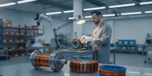
A dual winding motor can provide two winding sets for distinct operating states, electrical functions, or other application-defined needs. The presence of a second winding does not by itself provide backup operation, fault tolerance, more torque, or higher efficiency. Those outcomes depend on the complete motor and drive configuration, and require defined requirements and evidence. This guide describes how to frame the architecture decision and what to resolve before design release.
What does the term dual winding motor describe?
A dual winding motor has two winding sets associated with its electromagnetic structure. That broad description does not define how the conductors are arranged, whether circuits are isolated, how the sets are connected, or which states are permitted. One design may assign a winding to each of two operating modes. Another may use separately controlled sets in a shared magnetic structure. Some designs may allow concurrent operation; others may explicitly prohibit it. These are different architectures, even if a short product description uses the same name.
Start with a schematic and a terminal definition, not with an assumed benefit. Record each set’s phase and slot arrangement, winding direction, conductor and turn data, resistance and inductance over relevant conditions, neutral or shared connections, insulation boundaries, and connection to the drive. Identify which terminals are exposed at the motor interface and which connections are internal. The drawing and requirements should make it possible for a reviewer to determine what is connected, what is isolated, and what each winding is intended to do.
The phrase can also be confused with a tapped winding, a multi-phase motor, or a motor with connections changed to support different supply or speed conditions. Those terms may describe other electrical arrangements. A dual-winding label is not enough to infer the number of phases, a speed relationship, voltage options, or safe switching behavior. A useful specification names the construction and gives a circuit representation that matches the physical design revision.
For early discussions, use a winding map and state diagram. On the winding map, label each set and its terminals. On the state diagram, show which set is energized, what the drive does with the other set, and what event causes any transition. These two simple records make it easier for motor, controls, systems, manufacturing, and test teams to identify differences in assumptions before they become design changes.
What application requirements might justify two winding sets?
The rationale should begin with a requirement that cannot be met as effectively by a simpler architecture. One possible case is an application with two distinct operating conditions that need different electrical behavior. For example, a mechanism might need a continuous motion state and a separate low-speed adjustment state. The engineering team could investigate whether two windings and an appropriate drive arrangement meet those needs. It must still compare that design with a single winding and control strategy, a separate motor, or another system solution.
A second case may involve separating electrical functions within one assembly. That can be useful to explore when system interfaces, operating modes, or control responsibilities are distinct. But separation at the winding does not necessarily mean isolation across the whole system. The power source, control electronics, grounds, connectors, mechanical load, rotor, shaft, bearings, cooling path, and mounting may still be shared. Write down exactly which boundary is meant by separate: copper circuit, insulation system, drive channel, power source, sensing, connector, or supervisory control.
A third motivation sometimes raised is continued function after a fault. Treat this as a system-level design objective, not an inherent property of having another winding. Define the fault to be addressed, such as an open circuit in one set or a specified drive fault, then examine detection, isolation, allowable transition, resulting operating capacity, and safe shutdown. A shorted winding, common power fault, controller fault, damaged shaft, or loss of cooling may have a different consequence. If continued motion is required, specify the minimum acceptable motion and duration under the fault condition, along with the conditions in which the requirement applies.
The project team should state why the second set is under consideration in measurable terms. Flexibility and robustness are not acceptance criteria. A testable rationale might state that the motor must perform two listed duty profiles while staying within named current and temperature limits, or that a defined fault must be detected and place the mechanism in an identified safe state. This clarity can reveal that the winding count is only one part of a wider system change.
Which architecture decisions should be made before detailed design?
Document the intended operating states and forbidden states early. A state table makes the review concrete and prevents a schematic from silently implying a mode that the application has not approved. The following table is a starting checklist; its entries need to be completed for the named motor, drive, and revision.
| Decision area | Define for the project | Review question |
|---|---|---|
| Operating state | Active winding set, permitted overlap, start and stop behavior, transitions | Can every allowed state be represented unambiguously in the controls and test plan? |
| Electrical boundary | Isolation, shared nodes, terminal layout, grounding, insulation requirements | What exactly is independent, and what remains common? |
| Load and duty | Torque, speed, motion profile, duration, reversals, starts, ambient conditions | Which state or transition drives the most demanding electrical and thermal condition? |
| Fault response | Fault cases, detection method, action, required behavior, safe state | Is a response claimed only for faults that are defined and tested? |
| Controller interface | Drive channels, switching, feedback, inhibits, protection thresholds | Can the controller prevent an unintended or unsupported combination? |
| Package and process | Envelope, mounting, connectors, sealing, cooling, assembly and inspection | Can the specified construction be built and verified at the required interfaces? |
After agreeing on the table, draw each mode as a circuit state. For each row, show winding terminals, switching elements, drive channel, sensing, and the state of any inactive circuit. Do not label an inactive winding simply inactive if the terminals remain connected to a drive, are shorted, or can be induced to a voltage. These conditions can have different electrical and thermal consequences.
Use precise definitions throughout requirements and reviews. If a winding is called independent, name the degree of independence. If a mode is called backup, tie that term to the fault, load, duration, and remaining system components covered by evidence. If the design supports two speeds, describe the actual speed points, load conditions, and changeover method rather than treating two windings as proof of a speed capability.
How do winding connections affect electrical behavior?
Turns, conductor dimensions, winding distribution, phase arrangement, resistance, inductance, and connection scheme all contribute to behavior. A design evaluation should consider each winding separately and every permitted combination. Relevant conditions include supply range, current limits, back electromotive force, torque demand, speed range, drive modulation, and transient loading. The electrical model should represent the actual motor configuration, not just a nominal winding value without temperature, tolerance, and connection context.
Where sets share a magnetic circuit, energizing one set can affect the voltage induced in the other. Engineers should determine the behavior of the inactive set under the intended operating states. For example, an open-circuit set, a set connected to a disabled drive, and a set deliberately shorted are not equivalent conditions. The drive input protection and switching arrangement should be reviewed against voltages and currents that may arise from rotation, coupling, or a transition. Measurement and analysis should match the specific winding layout and operating envelope.
If both windings may operate at once, define how current and magnetic fields relate. Establish whether the electrical design permits concurrent energization, what phase alignment is required, which control channel regulates each set, and how each channel responds to load or current variation. The architecture must account for interactions between the sets, controller coordination, sensing, and protection. Do not infer that two drives can simply be connected to one motor because the motor has two sets; confirm the connections and allowed control behavior in the approved design.
If only one set is active at a time, switching still needs engineering. Specify the sequence for reducing current, confirming a safe switching condition, changing the selected circuit, and initiating the next mode. The correct sequence depends on the topology, controller, speed, load, and application. Define whether the mechanism may coast, must hold position, or needs a controlled transition. Determine how the system responds if the requested change cannot complete or feedback is missing.
A practical electrical review can compare a few named cases: normal operation on set A; normal operation on set B; an allowed transition from A to B; the inactive set under each active state; startup and shutdown; and each defined fault. For each case, record supply, connection state, commanded current, measured or predicted voltage, protective action, and acceptance limit. This gives design and test teams a shared basis for checking the schematic, firmware, and physical motor.
How should torque, speed, and duty be compared?
Translate application language into an operating profile before comparing winding designs. “High torque,” “slow movement,” or “intermittent use” is too vague to size and validate a motor. Describe the load over time: required torque, speed, acceleration, direction changes, dwell, starts per hour or cycle, and any holding requirement. Include the mechanical transmission and external load when they affect motor demand. Mark which portions of the profile use each winding set and whether a transition occurs while the load is moving.
Build a mode-by-mode performance matrix rather than one headline rating. For every mode, specify the required torque-speed region, supply range, current or power limits, duration, and allowable thermal condition. Include transient demands such as acceleration or load changes if they are part of the application. A winding selected for one mode may have different limits in another, and a rating from one set should not be carried over to another without supporting analysis and test evidence.
As a worked example, suppose an industrial actuator is expected to run a repeated positioning cycle and also perform occasional fine adjustment. First break the cycle into motion segments and dwell periods. For each segment, capture load, speed, time, and direction; then mark which state the proposed architecture assigns to that segment. Next estimate or measure the motor-side demand after accounting for the transmission and mechanical losses that the design team has established. Finally, review current, voltage, transition timing, and temperature across the entire repeated cycle. This process may show that two winding sets help meet distinct electrical conditions, or it may show that one winding and a different control profile should remain in the comparison.
Do not compare peak torque values without their duration, speed, voltage, cooling, and winding context. A short-duration point and a continuous operating requirement answer different questions. Likewise, a motor’s maximum speed alone does not establish that the required load can be driven at that speed. Every claimed point should identify the tested configuration and conditions, including the motor, controller, firmware or settings where applicable, mounting, and revision.
For a mode transition, analyze the load during the interval as well as before and after it. A system may experience a torque interruption, speed excursion, or changed holding behavior depending on the implementation. Determine whether the load can safely coast, whether the motion controller can tolerate a gap, and what happens if the transition is interrupted. These practical requirements can determine whether two electrical modes are useful in the application.
What thermal questions change when there are two windings?
Additional copper and insulation occupy space and influence slot fill, resistance, and paths for heat transfer. The design review should consider temperature in every allowed operating state, not only the mode with the highest steady current. One set can warm the shared stator structure and indirectly heat the other set. A winding that is electrically inactive may therefore still experience a thermal condition that needs to be assessed. Repeated switching between modes can also create a different heat history than a steady run at either mode alone.
Start with the duty profile and cooling boundary. Record ambient temperature, mounting orientation and contact conditions, enclosure, airflow or other cooling provisions, nearby heat sources, and the expected duration of each mode. Then evaluate the highest heating cases, including overlap if permitted, repeated transitions, and the application cycle that produces the least opportunity to cool. Consider startup, stall or overload events only to the extent that the system requirements allow them and the protections address them.
Identify material and component limits for the actual construction. Conductors, insulation, impregnation or over-molding materials, terminals, sensors, and nearby electronics may have different constraints. A general material property does not establish a complete motor’s permissible operating temperature. The winding arrangement, assembly process, heat transfer, sensor position, and controller response all matter. Specify where temperature is measured or estimated and how that evidence relates to the limiting location.
A useful thermal plan compares expected heat generation and dissipation for a representative cycle, then verifies the most relevant conditions with a test setup that resembles the application. Record the motor revision, mounting, enclosure, cooling, supply, load, speed, mode durations, transition intervals, sensor locations, and stabilization or stopping criteria. If the measured temperature differs from analysis, investigate the discrepancy instead of adjusting an unverified limit. Check whether the actual duty, cooling path, or winding resistance differs from the assumed condition.
Harsh or confined environments may limit heat rejection. Include those restrictions in the mechanical and electrical package review. If an integrated controller adds heat near the motor, examine the combined assembly rather than reviewing the motor in isolation. The same applies to a sealed enclosure or a mounting interface that changes conduction. These interactions should be captured in the design definition and the validation plan.
What should the controller do in each state?
Define control behavior as part of the motor architecture. Specify whether each winding uses a dedicated drive channel, whether switching hardware changes connections, or whether another arrangement is proposed. Identify how the controller determines the requested mode, what conditions permit a transition, how an unintended command is blocked, and what feedback is required. Include startup, shutdown, reset, inhibit, loss-of-feedback, undervoltage, overcurrent, and temperature-response behavior where applicable to the system.
Every state should have explicit outputs and constraints. Describe the active drive, current command, sensing inputs, allowed direction and speed, and the expected treatment of inactive winding terminals. Add interlocks to prevent prohibited states, such as energizing a combination that has not been designed and tested. If the controller has a fault response, state the sequence: how the fault is detected, how the condition is contained, what switching occurs, and what motion or safe state follows. Choose detection and protection thresholds from analysis and validation for that configuration.
For concurrent operation, review current regulation, phase relationship, commutation coordination, and interactions between channels. For alternate operation, confirm the transition sequence under representative speed and load rather than only at rest. In either case, ensure the motor interface, controller hardware, firmware, and system command logic agree on the same state definitions. A mismatch between a motor drawing and controller assumptions can undermine otherwise correct component-level analysis.
Integrated packaging adds interface questions. Define connector pins, grounds, feedback signals, shielding if required by the design, inhibit behavior, heat flow, sealing boundary, and access for assembly or service. A hermetic package needs a clearly defined motor-controller interface and a review of the feedthroughs, connections, and heat path. The phrase custom hermetic motor controller should refer to a project-specific requirement and configuration, not to a universal rating. Composite Motors describes custom brushless AC and DC motors, controllers, and hermetically packaged electronics; project requirements determine the applicable design scope.
When the system needs controller development alongside a motor, review the available custom BLDC controller information as one part of an engineering discussion. It does not replace a project interface specification. Bring the motor state table, winding schematic, supply limits, feedback requirements, and defined fault behavior to that review.
How do physical packaging and manufacturing affect the choice?
Two winding sets influence more than electrical drawings. They affect slot area, insulation placement, lead routing, terminal identification, assembly access, and inspection. Check whether the selected construction fits the motor envelope, shaft and mounting interfaces, connector position, enclosure, and cooling arrangement. If the motor must fit an existing mechanism, provide the controlling dimensions and tolerance requirements, plus any access restrictions for installation and connection.
Review winding feasibility with the intended process. Can the specified conductors and insulation be placed consistently in the available geometry? Can leads be routed without violating bend, clearance, or assembly requirements? Can each winding be identified at the relevant build and test stages? Are the terminations accessible for inspection and electrical testing? These questions should be answered by the design and manufacturing teams using the actual construction, not by assuming that a second set is merely a duplicate of the first.
Consider process sequence when the assembly includes over-molding, hermetic packaging, precision machining, integrated electronics, or other manufacturing operations. A process can affect access to leads, inspection points, and interfaces. Establish how materials, process steps, critical dimensions, and design revisions will be controlled. Decide which characteristics are verified during winding, assembly, final electrical test, or another defined inspection. The inspection method needs to distinguish the two sets and confirm the required connections without ambiguity.
Build-to-print and custom design projects call for different inputs. In build-to-print work, provide controlled drawings, material callouts, process notes, terminal definitions, acceptance criteria, and revision history. Identify incomplete or conflicting information rather than silently resolving it. In a custom design effort, separate firm requirements from preferences and identify decisions that remain open. This helps the team compare concepts before details become embedded in tooling, fixtures, or test procedures.
For an application-specific motor program, the manufacturing plan should cover traceability between the motor, its winding data, the controller interface, and the test record. Define how changes to wire, slot layout, insulation, winding connection, packaging, firmware, or tooling are reviewed. A change that appears small can alter electrical or thermal behavior. Agree on change review and any needed re-analysis, inspection, or retesting before production release.
Composite Motors lists engineering and manufacturing activities including stator winding, over-molding, precision machining, assembly, reverse engineering, and testing. The motor engineering and manufacturing services page can help teams understand the described scope. Whether a particular process or program is appropriate depends on its requirements and agreed project definition.
How should engineers define fault response without overclaiming?
Start with a fault list and a boundary. State whether the analysis covers the motor alone, the drive, the power supply, the controller, the mechanism, or the complete system. A winding fault does not have the same implications as a supply interruption or mechanical jam. For each fault, describe how it is detected, whether detection is possible in the required time, what the control system does, and what behavior is acceptable afterward.
Separate fault prevention, fault detection, fault containment, and continued operation. These are not interchangeable. A design may detect a condition and stop safely without supporting continued motion. It may isolate one electrical path but retain common failure points in power, control, connectors, rotor, shaft, bearings, or cooling. If the requirement is for continued function, identify the precise available operating state after the fault and the performance needed in that state. Specify duration and any restrictions on load or speed.
Build a fault-response matrix. Example columns include initiating condition, observable signal, detection rule, commanded action, expected motor state, system-level outcome, and verification method. Include normal operation and transition cases as well as faults that the system hazard or reliability analysis identifies. Do not assume a second winding makes a fault harmless. A short circuit can produce different behavior from an open circuit; an undetected fault may prevent a requested mode change; and a common controller or supply failure may affect both sets.
Then plan safe and representative tests for the claims the project makes. Define the test article and configuration, fault injection or simulation method, instrumentation, protective measures, load, environmental conditions, acceptance criteria, and reset or post-test inspection. For conditions that cannot be reproduced safely or economically, document the analysis and its limits. A test of one winding condition does not automatically establish behavior for another fault or a different design revision.
How can a team compare architectures fairly?
Keep the dual-winding concept in a comparison with credible alternatives. Depending on the requirement, candidates might include a single winding with a different control strategy, a modified standard motor, separate motors, a mechanically changed system, or a different motor-and-controller integration. No option is universally preferable. Compare them against the same duty, interface, environmental, fault-response, and manufacturing requirements.
For each candidate, record what it satisfies, what it cannot satisfy, what assumptions are open, and what evidence exists. Include controller complexity, wiring and connector needs, cooling, packaging volume, assembly steps, test coverage, and design-change exposure. Note common components that remain shared in any proposed fault-response strategy. This avoids comparing a fully defined dual-winding design against an under-specified alternative, or judging one architecture on a benefit that another was not allowed to address.
A simple decision workshop can proceed in four steps. First, review the requirement list and remove adjectives that do not have acceptance criteria. Second, identify the most difficult operating state and transition for each architecture. Third, list the analyses, samples, and tests needed to reduce the main uncertainties. Fourth, decide whether the expected application value justifies the extra winding, controller, interface, manufacturing, and verification work. Capture the decision and unresolved risks so the rationale survives personnel and revision changes.
For instance, an actuator that has two clearly separated voltage or motion conditions could merit a study of separate winding arrangements. The comparison should still examine how each option delivers the required torque-speed profile, how it switches modes, what the controller must do, how heat accumulates during the cycle, and whether the added terminals fit the package. If those questions cannot be answered from available data, the correct next step is to define analysis and test work, not to advertise an assumed performance advantage.
What should a useful engineering specification include?
A first project brief does not need to pretend every design decision is settled. It should distinguish known facts, requirements, preferences, and unknowns. That distinction makes a technical review more productive and reduces the risk that an early assumption is mistaken for a final rating.
- Application and duty: Describe the mechanism, load, motion profile, torque, speed, direction changes, starts, dwell, cycle duration, and any holding or emergency behavior.
- Operating states: List each intended winding state, allowed overlap, transition conditions, startup and shutdown sequence, and prohibited combination.
- Electrical interface: Provide supply range, drive topology if known, current and voltage limits, feedback, terminals, grounds, protection, and any isolation requirements.
- Environmental conditions: Define ambient conditions, exposure, enclosure, mounting, cooling, vibration or other application constraints that are established for the system.
- Mechanical package: Give the envelope, shaft and mounting interfaces, connector location, installation access, and controlled dimensions or drawings.
- Fault requirements: Identify the fault cases of interest, detection needs, response, safe state, and whether any continued function is required.
- Manufacturing and validation: State quantities or volume expectations as project planning inputs, development stage, available samples, inspection needs, documentation, and required evidence. Do not treat a planning estimate as a performance claim.
- Configuration control: List drawing and firmware revisions, known changes, test records, and the authority for approving changes and acceptance criteria.
When information is missing, label it as a question and assign an owner. For example, if the inactive winding’s electrical state is unknown, the controls and motor teams should agree on the candidate states to evaluate. If the thermal boundary is unknown, identify the mounting and cooling conditions needed for representative testing. If fault behavior has not been established, have the system owner define the required outcome before selecting a winding arrangement.
Organizations evaluating custom brushless AC and DC motors can share a concise brief and supporting drawings through a project discussion. The design review can then establish which electrical, mechanical, manufacturing, and testing decisions need to be resolved for the specific application.
How should the design be validated?
Validation should demonstrate that a named configuration meets its stated requirements. Create a requirement-to-evidence matrix that maps each claim to analysis, inspection, or test. Record the motor and controller revisions, sample identification, setup, instruments, environmental conditions, and acceptance criteria. State whether a result applies to a prototype, an engineering sample, or the released configuration. Avoid generalizing from a test that covered only one mode or one operating point.
Begin with construction and electrical checks suitable for the design. These may include continuity, resistance, terminal identification, and appropriate insulation checks as specified for the project. Verify that each winding set corresponds to the controlled schematic and that inactive-state connections are correct. Review the controller and motor interface together. The precise tests and limits should be defined by the design and applicable requirements rather than borrowed from an unrelated motor.
Functional validation should exercise each permitted operating state and transition. Capture supply conditions, commanded and observed current, speed, load or torque measure, transition response, and protection behavior as appropriate. If concurrent operation is allowed, include it as a distinct state with its specified conditions. If it is not allowed, verify that the controller or system architecture prevents accidental entry into it. Exercise startup, shutdown, reset, and fault responses that are in scope.
Thermal testing should represent the specified duty, mounting, enclosure, and cooling boundary. Measure or estimate relevant temperatures at defined locations and record the profile, not only a final value. Use the operating cycle that challenges heat accumulation, including mode changes where relevant. If the measured condition differs from the expected one, investigate the cause and update the model, requirements, or design before accepting the result.
Mechanical, environmental, and endurance evaluations should follow actual application needs. A broad descriptor such as “harsh environment” does not define a test. Name the exposure, severity, duration, sequence, and acceptance criteria that the system requires. Include connectors, seals, feedthroughs, mounting, cable routing, and integrated electronics where they affect the intended package. Do not assume a motor-only test represents the complete assembly.
For fault claims, verify the defined detection and response safely under controlled conditions. Record how the fault was introduced, the system state before and after, time to response if relevant, resulting motion, and any damage or degradation criteria. A successful run supports only the tested fault and configuration. It does not establish resilience to untested faults or independent behavior of components that still share a supply, controller, mechanical assembly, or thermal path.
Finally, establish change-impact rules. A revised winding, conductor, insulation system, terminal arrangement, controller, switching strategy, firmware, package, or manufacturing process can invalidate some prior evidence. Review the change against the requirement-to-evidence matrix and decide which analysis, inspection, or test needs repetition. Preserve revision-controlled results so design, production, and future troubleshooting teams can tell which configuration was actually evaluated.
What questions should teams settle before release?
Before design release, ask whether the winding topology and allowed states are fully defined; whether every winding terminal and inactive state is documented; whether the duty profile and thermal boundary represent the application; whether controller protections match the approved design; and whether manufacturing can identify and inspect both sets. Check that packaging and connection interfaces fit the system and that any sealing or integrated-electronics constraints are included.
Then review the claims. Is the design described as supporting a mode only when that mode has been analyzed and verified? Is any backup or fault-response statement tied to a defined fault and system boundary? Do performance points name the applicable configuration and test conditions? Are unresolved assumptions identified, with owners and planned evidence? If any answer is no, the project may need more specification or validation before a release decision.
A release package should connect requirements, drawings, controller documentation, manufacturing instructions, inspection criteria, test procedures, test records, and change control. That evidence trail matters when the winding, controller, assembly, or intended use changes. It also helps ensure a claim remains accurate as the project moves from design into manufacturing.
Frequently asked questions
Does a dual winding motor automatically provide redundancy?
No. A second winding alone does not establish redundancy or continued operation after a fault. Define the fault, system boundary, detection and switching response, remaining shared components, operating requirement, and validation evidence.
Can both winding sets operate at the same time?
Only when the specific motor and controller are designed for concurrent operation and the electrical interaction, current regulation, thermal condition, and allowed state have been validated. Do not infer permission from the presence of two winding sets.
Is a dual-winding design necessarily a dual-speed motor?
No. The name does not specify speed points or how they are achieved. Define the winding arrangement, drive strategy, load conditions, and tested speed behavior for the particular configuration.
What should we provide for an initial design review?
Provide the application and duty profile, load and speed needs, intended operating states, supply and controller information, environmental and package limits, fault-response requirements, development stage, and available drawings or test data. Identify uncertainties rather than treating them as settled values.
What evidence supports a performance or fault-response statement?
Use configuration-specific analysis, inspection, and test records tied to defined requirements and acceptance criteria. The evidence should identify the motor, controller, revision, operating conditions, and the exact behavior demonstrated.
Tell us about your motor requirements
A dual-winding concept is worth pursuing when its purpose is stated as a verifiable application requirement and its electrical, thermal, control, package, manufacturing, and validation implications are understood. Treat each expected benefit as a design question to answer for the approved configuration.