


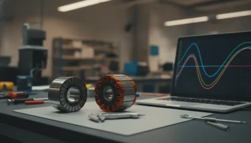
Brushless motor design calculations begin with the application duty, then connect electrical, magnetic, thermal, and mechanical inputs into one operating envelope. The result is not one universal torque, current, or temperature. It is a set of targets and limits for a named configuration, including voltage, speed, torque, temperature, geometry, feedback, and duty cycle. A useful calculation sheet makes clear which values are fixed, estimated, or still require testing.
Call (352) 752-7657 to discuss your motor design requirements or tell us about your project.
Start with application and electrical inputs
Begin with the job the motor has to perform, not an isolated catalog rating. Record the load, required motion, acceleration, stopping behavior, available DC bus voltage, target speed range, torque, and duty cycle. A short peak, a holding period, and a long run create different design checks. Keep peak torque and continuous torque separate, and record how long each operating point lasts.
For a first mechanical-power estimate, use P = T × ω, where T is torque and ω is angular speed. The U.S. Department of Energy motor-systems sourcebook provides related motor-system background. Electrical input power will be higher because the complete assembly has losses. Efficiency is therefore something to estimate and validate for the specified configuration, not a universal constant to assume.
| Input group | Record before modeling | Keep separate from |
|---|---|---|
| Electrical | Voltage window, current limits, speed, torque, duty | Thermal and mechanical ratings |
| Magnetic | Flux, winding, poles, slots, magnets, air gap | Measured production results |
| Thermal | Losses, ambient, cooling path, peak duration | A simulated temperature and a tested limit |
| Mechanical | Inertia, shaft loads, envelope, bearings, mounting | A page-level size range and a fit guarantee |
Voltage, current, and torque should remain in separate fields until a named model or test connects them. Record nominal, minimum, and maximum supply conditions. For a battery system, include the voltage at relevant points in the duty rather than only its nameplate value. Also distinguish controller supply current from motor phase current. They are different design inputs.
Rotor-position feedback and the controller approach belong on this first sheet because they affect commutation and motion control. Do not assume that a particular sensor or controller behavior is standard across every custom motor. The existing guide to designing a brushless motor controller is a useful related resource, but the named controller and motor configuration still determine the final requirements.
Translate magnetic inputs into a candidate geometry
Magnetic calculations connect the electrical targets to a stator and rotor. Typical inputs include pole and slot count, winding arrangement, turns, phase resistance and inductance, magnet material and geometry, air-gap length, stack length, and expected back-EMF behavior. These values interact. Changing winding turns can affect voltage constant, current requirements, copper loss, and usable speed range. Changing magnet or air-gap geometry can affect flux, torque production, saturation risk, and manufacturability.
Mark torque constant, back-EMF constant, and loss values as estimates until they are checked against the named configuration. A value copied from a similar frame size is not a released specification. If a sample exists, measure appropriate electrical properties on that sample before relying on a model. The measurements provide a comparison point, but they do not by themselves establish a thermal, protection, or reliability rating.
Motor electromagnetic simulation and finite element analysis can compare candidate geometries before hardware is built. The output depends on material data, geometry, boundary conditions, and manufacturing tolerances, so simulation needs engineering review. It is most useful when tied to measurable requirements and followed by prototype or production testing. A model can rank options; testing on the named configuration supports the result.
Need help connecting calculations to an application-specific motor? Review this brushless motor design resource and send the application requirements to the CMI team.
Check thermal, mechanical, and manufacturing limits
Electrical and magnetic results are useful only when the assembly can operate within its temperature and structural limits. Thermal inputs include winding copper loss, magnetic and core losses, bearing or seal losses, controller losses, ambient temperature, airflow or liquid cooling, peak duration, and the heat path through the housing and mounting structure. A motor that meets a temperature target in moving air may not meet the same target in a sealed package.
Mechanical inputs include load inertia, acceleration and deceleration, radial and axial shaft loads, bearings, shaft and mounting geometry, vibration, balance, connectors, and the available package. Include the length and diameter of the complete assembly, not only the active electromagnetic stack. The envelope may also need room for wiring, feedback hardware, controller electronics, and assembly access.
Manufacturability belongs in the calculation loop. Composite Motors documents custom design and build-to-print support, motor and mechanical design, finite element analysis, custom winding, injection over-molding, precision machining, assembly, and electrical and performance testing. Those are documented capabilities, not a promise of a fixed price, lead time, capacity, or universal rating. Materials, winding methods, tooling, tolerances, and test requirements should be reviewed against the particular design.
- Thermal: Does the winding stay within the limit for the specified duty and cooling path?
- Mechanical: Can the shaft, bearings, rotor, housing, and mount handle the required speed and loads?
- Manufacturing: Can the selected materials, winding, machining, over-molding, and assembly processes produce the geometry consistently?
- Validation: Which torque-speed, temperature, electrical, and inspection tests will confirm the model?
Use the calculation sheet in a design review
A calculation package is ready for a manufacturer when every number has an owner and a status. Label each value as a customer requirement, measured result, model estimate, or open question. Keep nominal, continuous, peak, and fault conditions distinct. If drawings disagree on stack length or the voltage remains a range, show the conflict instead of replacing it with a single unsupported number.
- Freeze the duty points: torque, speed, and time at each point.
- Freeze the supply window and current limits as separate fields.
- Evaluate magnetic geometry and identify which constants still require measurement.
- Name the cooling path, mechanical envelope, shaft loads, and feedback requirements.
- List the tests that will confirm the model on the named configuration.
Composite Motors can review an existing design for manufacturability, adapt a design, or start from application requirements. Its motor and controller manufacturing services page describes design, winding, over-molding, precision machining, assembly, and testing paths. Bring the duty sheet, available drawings, package constraints, environment, and test requirements to the project discussion.
Call (352) 752-7657 to discuss your brushless motor design calculations or contact Composite Motors about the application and manufacturing path.
Frequently Asked Questions
What inputs do brushless motor design calculations require?
They require the duty, voltage window, continuous and peak current limits, speed, torque, cooling path, mechanical envelope, environment, and feedback needs. Magnetic constants should be marked as estimates until the named configuration is checked.
Why are torque and speed not enough?
They do not describe how long the motor must produce the load, how quickly it must change speed, what voltage is available, or how heat leaves the package. Those conditions can change winding, controller, cooling, bearing, and enclosure decisions.
When should a manufacturer be involved?
Involve a manufacturer when the duty points, supply window, and envelope are documented, even if some magnetic values remain estimates. Early review can connect the calculations to winding, materials, tooling, assembly, and testing.